Water supply installation
Site water supply
The site water supply will be executed from PEHD PN10 (high density polyethylene) pipes and fittings, laid on a sand base of at least 15 cm. The backfill is sand up to 30 cm above the pipe bottom and non-standard ballast to ground level. Immediately above the pipe bottom, a detector tape should be laid, and after the main backfill and before the final restoration of the upper surface of the excavation - a warning tape to mark the exact location and protect the water supply.
Building water supply installation
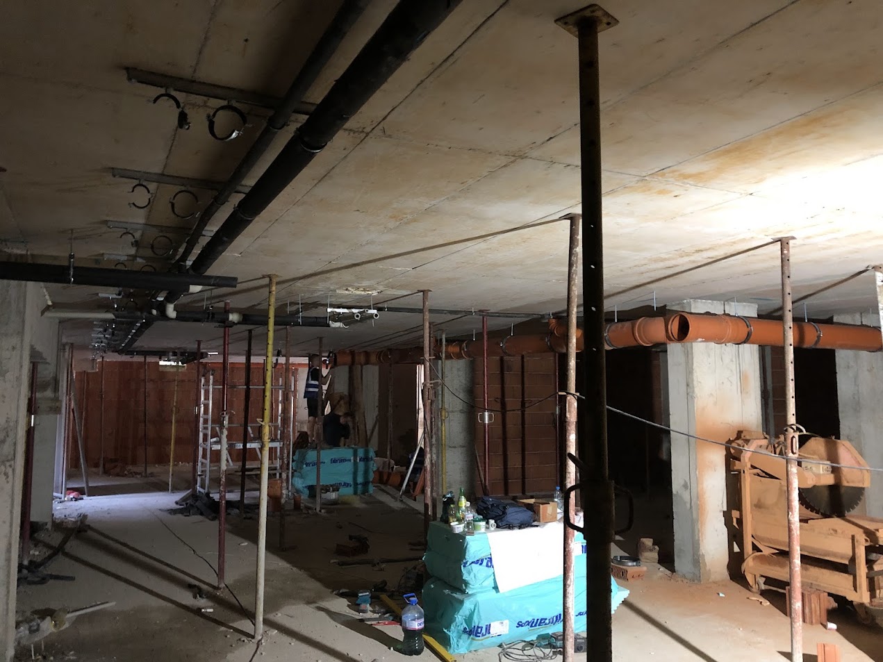
The building water supply installation includes a horizontal suspended water network (HSWN), vertical water branches (VWB) and floor distribution network. HSWN is suspended in the basement by brackets to the structural elements of the building. At the branches from HSWN to VWB and at the floor branches, shut-off valves with drain are provided.
The main horizontal water branches, vertical branches and floor distribution installation for cold water will be executed from pipes and fittings system of polypropylene PP.
The main horizontal water branches, vertical branches and floor distribution installation for hot and circulation water will be executed from pipes and fittings system of polypropylene PP Stabi with aluminum insert.
The water supply installation for fire protection needs will be executed from galvanized steel pipes and fittings.
All brackets and fastening elements on the water pipes should be executed with corrosion protection and sound insulation pads.
When hidden installation of the pipe routing in the wall, it is necessary to comply with the requirements of the specific pipe manufacturer for safe installation.
Regardless of the type of pipes, the installation is thermally insulated along its entire length - buried and open, thermal insulation with microcellular structure (non-combustible) should be made.
Minimum thickness of thermal insulation:
- Installation for hot and circulation water from DN20 to DN25: 26 mm
- Installation for hot and circulation water from DN25 to DN50: 40 mm
- Installation for hot DN50: 60 mm
- Installation for hot DN63: 70 mm
- Installation for cold water from DN20 to DN40: 6 mm
- Installation for cold water from DN50 to DN90: 10 mm
Maximum distances between supports for steel pipe system:
DN20: 2.0m | DN25: 2.25m | DN30: 2.75m | DN40: 3.0m | DN50: 3.5m | DN60: 4.0m | DN75: 4.25m | DN90: 4.75m
Maximum distances between supports for polypropylene PP stabi pipe system:
DN16: 1.3m (vertical) / 1.0m (horizontal)
DN18: 1.3m (vertical) / 1.0m (horizontal)
DN20: 1.3m (vertical) / 1.0m (horizontal)
DN25: 1.95m (vertical) / 1.5m (horizontal)
DN32: 2.6m (vertical) / 2.0m (horizontal)
DN40: 2.6m (vertical) / 2.0m (horizontal)
DN50: 3.25m (vertical) / 2.5m (horizontal)
The fastening of the main supply water branches should be carried out to the structural elements of the building (beams, columns, etc.).
The execution of the water supply installation must be carried out by specialists well acquainted with the requirements for installation of steel and polypropylene PP pipe systems in strict compliance with the specific requirements of the manufacturer.
Disinfection of water supply installation
The water supply installation in the building before commissioning is disinfected and flushed in compliance with sanitary and hygienic requirements.
Disinfection should be carried out by chlorination using a mobile chlorination station working with gas, with the amount of chlorine supplied to the installation for 10 min being 5mg/l.
During disinfection, measures should be provided to prevent the entry of the disinfecting mixture into the city water supply system, for which purpose the shut-off valve located immediately after the pipe enters the building should be closed.
The water for disinfection should be taken from the street water supply system.
After completion of disinfection, flushing of the installation should be done using water from street water supply, with the shut-off valve located immediately after the pipe enters the building open.
The waste water from disinfection and flushing of the water supply should be collected and discharged into the domestic sewerage.
The selected disinfectant, namely chlorine gas, is not aggressive to the material of the water supply and sewerage installations.
Sewerage
For drainage of the facility, it is planned that after reconstruction, reconstruction of existing buildings and a new hotel building, it will be in an existing ID400mm channel from polypropylene pipes passing along the axis of "Vasil Levski" street.
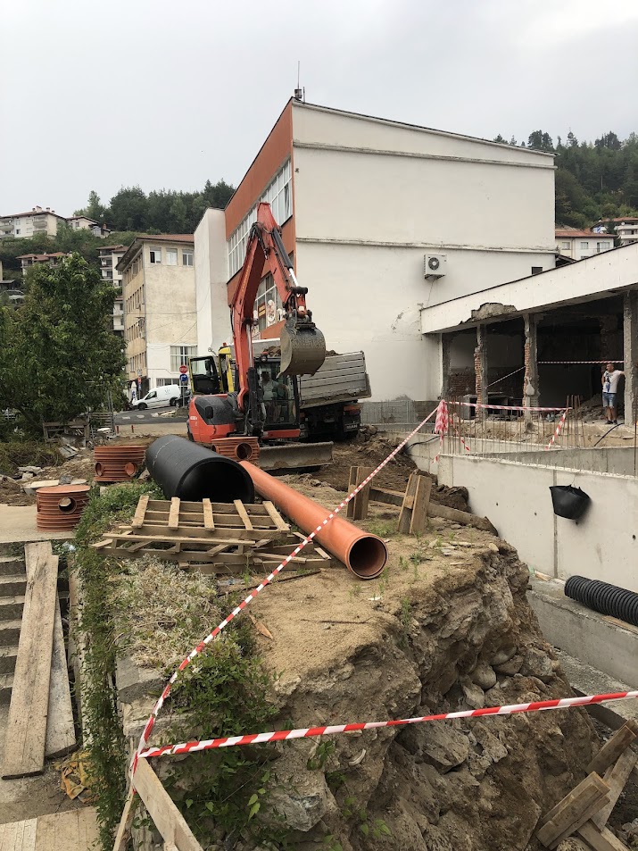
For this purpose, two new building sewer branches will be built, and the existing Ф200 will be removed after the execution of the first two. The first new sewer branch from thick-walled PVC pipes SN8 Ф300mm will discharge waste domestic and atmospheric water from existing and new hotel building and extension in basement at level -6.00. Before leaving the building, a main inspection opening is built with bottom pipe level -4.80.
The second sewer branch from PVC pipes SN8 Ф200mm drains the waste water of the existing restaurant building after reconstruction. For inspection and operation, a new site inspection shaft Ф800mm is built at the beginning of the branch in green areas.
The connection to the existing street channel pipes Ф400mm is made in existing street inspection shafts with compliance with requirements: the bottom level of the connecting sewer branch should be above the bottom level of the discharging street collector and the water level of the branch is above the water level in the shaft at maximum hydraulic conductivity of the discharging street channel.
The longitudinal and typical cross profiles of the sewer branches are given in the project for "VIK connections".
The existing site network is removed except for 2 inspection shafts, which will be used during reconstruction and new construction.
Note: During execution, the sequence of construction should be observed, so that the removal of the site network and existing branch follows the execution of the new building sewer branches.
The building sewer installation is gravity-separate with mixing of domestic-fecal and rainwater waste water in the basement. Ventilation is basic. The waste water from the restaurant kitchen is discharged into the sewer installation after local grease treatment in an under-sink separator 50l at level +0.95.
Rainwater from the roof and terraces is discharged by water receivers according to BDS EN1253-2, linear drains and polypropylene downpipe system.
Condensate from air conditioners is discharged by PVC drain installation and discharged into the downpipes on the ground floor and at level -3.00.
Before mixing the building rainwater sewerage into the suspended sewerage for mixed waste water in the basement, a hydraulic seal (siphon) is provided according to detail.
Condensate from internal air conditioner units in the buildings is discharged by PVC condensate pipe installation Ф25mm, which are discharged at a suitable place in the downpipes of the corresponding floor. For some of the internal units, the discharge is made into the drain branch of the sanitary fixture through a built-in condensate siphon for wall.
Drainage of the two basements will be done by:
- Point drains (floor siphons) at level -3.00 from cast iron class В125 according to BDS EN1253-1 and discharge to suspended sewerage for gray water and 2 pcs. vertical branches respectively at levels -3.00 and -5.80.
- Linear drains at level -5.80 with grates class В125 according to BDS EN1433.
The waste gray water from the garages in the 2 basements will be treated from 1 pc. buried in the foundation oil separators at level -5.80 and subsequent discharge of the water from 1 pc. buried in the foundation pump in drainage shafts to suspended mixed sewer installation at levels -3.00.
The connection of the pressure pipelines to the gravity sewerage should be made with a reverse siphon.
Sizing of waste water quantity according to BDS EN12056-2, point 6.3.1